
How a 3D vehicle scan becomes a PPF cutting pattern
The practical workflow is scan → clean → define coverage → flatten → inspect → cut → test fit. The hard part is not making a mesh lie flat. It is keeping the installer’s intent intact while showing where flat film has to stretch across a curved panel.
Input
STL · OBJ · PLY
Output
SVG · DXF · PLT
Required check
physical test fit
 3D scan 2D cutting template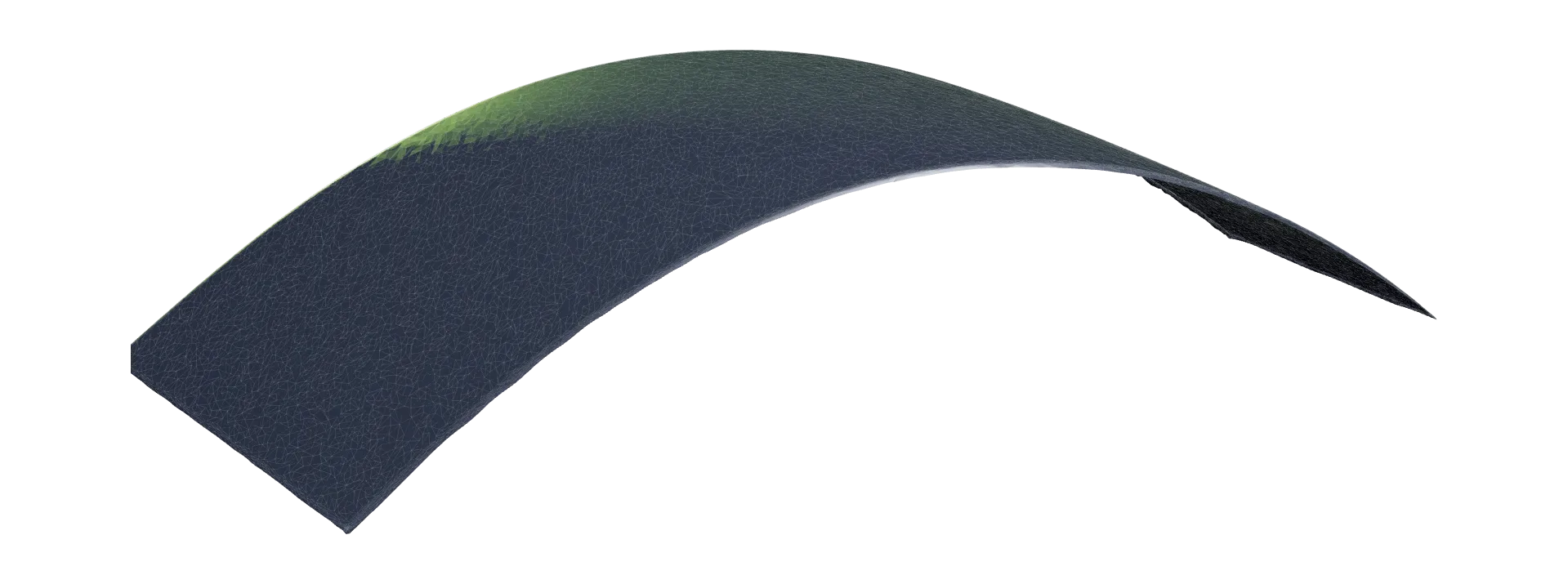
The scan-to-pattern workflow
Each stage protects a different kind of accuracy: measurement, surface quality, installation intent, the film’s stretch budget, plotter geometry and real-world fit.
- 01
Capture the panel surface
Scan the actual vehicle panel with a structured-light or laser scanner. Export a surface mesh as STL, OBJ or PLY. The mesh is the measured starting point, not the final cut path.
- 02
Clean only what affects the pattern
Remove floating geometry, fill the gaps that matter and reduce scan noise, without sanding away the character lines, openings and panel edges that decide the fit.
- 03
Define coverage and seams
Choose the protected region on the real surface. Place seams where the installer can hide or manage them, then set edge wraps and reliefs before flattening.
- 04
Flatten the curved mesh
Convert the selected 3D surface into a two-dimensional mesh. A useful flatten does more than lie flat: it reports stretch, compression and shear face by face, so the installer can judge how the film will behave before anything is cut.
- 05
Check the pattern against the film
Run the numbers on the actual cut shape. Where does the film have to stretch past its working limit? Where is there more film than surface, and can that excess be worked out to a free edge or will it fold? A wrinkle caught on screen costs a seam or a relief cut. One discovered on the car costs the piece.
- 06
Edit, add cutouts and export
Adjust anchors, seam positions and edge offsets. Round features are measured, not traced: a parking sensor is detected from its bezel ring on the scan, confirmed by hand and cut with a margin the installer sets. Then export SVG, DXF or PLT for the plotter, with the scan and every decision kept editable.
- 07
Test fit before production
Cut cheap test material or a sacrificial film piece, check the alignment on the vehicle and feed corrections back into the digital pattern. Scanning takes out the guesswork, but it does not replace checking the fit on the car.
What “measured” looks like on screen
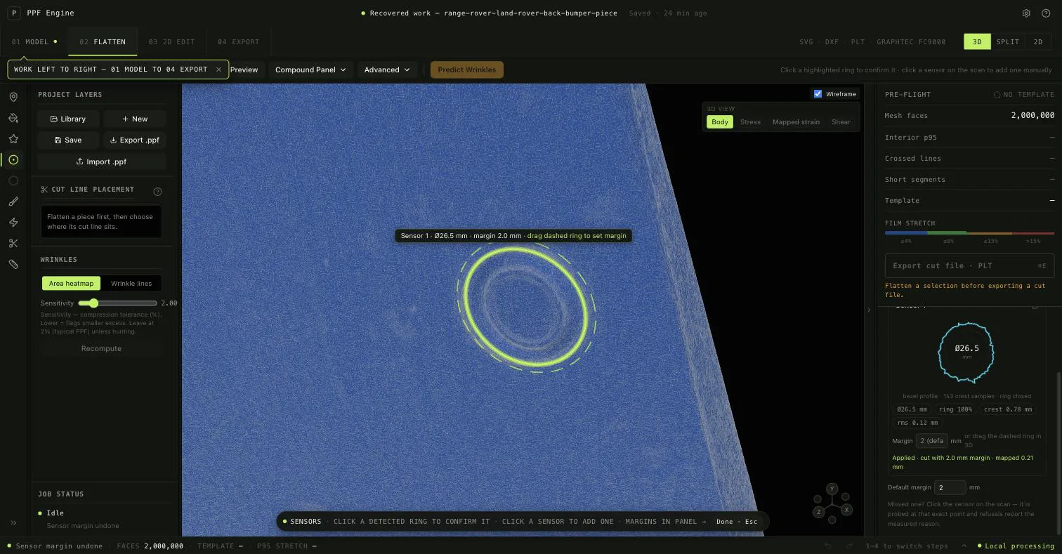
This is the flatten step on a Range Rover rear-bumper scan: two million faces, processed locally. The detector has found a parking sensor and fitted a circle to its bezel. It measured Ø 26.5 mm, a fully closed ring and 0.12 mm RMS across 143 crest samples. Nothing is cut on trust. The installer clicks the glowing ring to confirm the sensor, then drags the dashed ring to set the cut margin with a live readout in millimetres. Here it sits at 2 mm.
The pre-flight column sits next to the export button on purpose. Crossed lines, short segments, interior stretch and the film’s stretch budget are all checked before a cut file ships. The hole itself follows the sensor’s true developed shape after flattening, not an idealised circle traced by eye.
Sensor
Ø 26.5 mm · ring closed
Cut margin
2.0 mm · set by drag
Scan
2,000,000 faces · local
Scanning, flattening and pattern making are different jobs
A scan is not a template
A mesh describes a curved surface. A production pattern also needs coverage boundaries, seams, reliefs, wraps and a cut path the plotter can follow.
Flattening is not tracing
Tracing a photograph ignores compound curvature. Mesh flattening starts from measured surface geometry and makes distortion visible before film is cut.
The installer stays in control
Software can calculate and flag. The installer decides where a seam belongs, how far an edge wraps and whether the result is workable on the car.
A draft is not a production file
Sometimes a measurement falls short: a sensor ring that never fully closed, a flatten that fails its stretch check. The pattern still exports, but it goes out marked as a draft with the evidence attached. The gap is recorded, not hidden.
What scanner do PPF installers need?
Any scanner that exports a usable mesh can enter the workflow. An entry-level structured-light handheld is enough to prove the process works on your own panels. Higher-end structured-light and laser scanners generally make cleanup faster and hold on to small features more reliably.
Choose based on the panels you actually pattern, the accuracy you need, capture speed and how much mesh cleanup you are willing to do, not on a software badge. PPF Engine works with whichever scanner you pick, and the patterns you make are yours either way.
See the scanner and plotter compatibility guide for what we have tested ourselves, and PPF Engine vs ExactFlat if you are weighing a CAD-based flattening tool.
Build the pattern while the vehicle is in your shop
PPF Engine is desktop pattern software for installation shops and independent installers. Your scans and patterns stay on your machine.